INA219 Power Sensor
How to Read the INA219 Sensor Module Using Arduino? The INA219 Sensor Module is a sensor that can measure current, voltage, and power.

The voltages that can be read are the shunt voltage, the bus voltage, and the load voltage. The voltage will be read on a 0.1 ohm shunt resistor with a tolerance of 1% 2W.
On page 5 in the datasheet, it is written that the maximum voltage reading of the shunt resistor if PGA = 8 is ± 320mV, which means INA219 will be able to read a maximum current of ± 3.2A.
INA219 sensor has a 12-bit internal ADC. This means that the reading value will be divided into 4095 samples. If we use a maximum current of ± 3.2A, the value will be divided by 4095.
3.2A / 4095 = 0.000781441 A
So, the sample will detect a current of 0.000781441 A or 0.78 mA (± 0.8 mA). This will make a precise current reading.
The maximum voltage that can be read is up to ± 26VDC even though this module only uses 3 or 5V VCC source voltage.
For communication with a microcontroller, this sensor uses I2C communication which can be connected to the Arduino. we using 2 pins only, SDA on pin A4 and SCL on pin A5.
The INA219 sensor module has two input pins IN + and IN- connected to the shunt resistor. To be able to use this module, we need a library that will make Arduino programming easier.
INA219 Arduino Library
The INA2019 Sensor library is available in the Arduino IDE library manager. Please add it to your Arduino IDE with these steps:
- Click the Sketch menu
- Click Include Library
- Click Manage Libary
- Then type on search form “Adafruit INA219“
- Click install
This library, in addition to measuring the current in the shunt resistor, can also read the NA219 Arduino Voltage shunt, load voltage and bus voltage. You can see this voltage difference in the following picture:

I2C Address
A reference I2C Address INA219 module to this library:
Jumper A0 Jumper A1 Alamat I2C Not Connected Not Connected 0x40 (Default) Connected Not Connected 0x41 Not Connected Connected 0x44 Connected Connected 0x45
INA219 Arduino Wiring
The circuit between the Arduino Uno and INA219 is very simple, you just connect:
- VCC to 5V or 3V.
- SCA to A4 pin
- SCL to pin A5
- GND to GND
Consider the following picture, in the example the load here is measuring the current flowing from the solar panel to the Load, you can replace this load into other devices such as LEDs, lamps, other electronic devices and so on:

Basic Code
In this article I connected jumper A0 then I used the I2C address of the sensor module is 0x41. Here is the Arduino code that I provide and please upload it to your Arduino.
#include <Wire.h>
#include <Adafruit_INA219.h>

// Adafruit_INA219 ina219;        //Default adress is 0x40
Adafruit_INA219 ina219 (0x41);    // if A0 is jumpered
// Adafruit_INA219 ina219 (0x44); // if A1 is jumpered
// Adafruit_INA219 ina219 (0x45); // if A0 and A1 is jumpered


void setup(void)
{
  Serial.begin(9600);

  if (! ina219.begin()) {
    Serial.println("Failed to find INA219 chip");
    while (1) {
      delay(10);
    }
  }

  // By default the initialization will use the largest range (32V, 2A).

  // To use a slightly lower 32V, 1A range (higher precision on amps):
  //ina219.setCalibration_32V_1A();

  // Or to use a lower 16V, 400mA range (higher precision on volts and amps):
  //ina219.setCalibration_16V_400mA();
}

void loop(void)
{
  float shuntvoltage = 0;
  float busvoltage = 0;
  float current_mA = 0;
  float loadvoltage = 0;
  float power_mW = 0;

  shuntvoltage = ina219.getShuntVoltage_mV();
  busvoltage = ina219.getBusVoltage_V();
  current_mA = ina219.getCurrent_mA();
  power_mW = busvoltage * current_mA;
  loadvoltage = busvoltage + (shuntvoltage / 1000);

  Serial.print("BUS: ");
  Serial.print(busvoltage);
  Serial.print(" V     ");

  Serial.print("SHUNT: ");
  Serial.print(shuntvoltage);
  Serial.print(" mV     ");

  Serial.print("LOAD: ");
  Serial.print(loadvoltage);
  Serial.print(" V     ");

  Serial.print("CURRENT: ");
  Serial.print(current_mA);
  Serial.print(" mA     ");

  Serial.print("POWER: ");
  Serial.print(power_mW);
  Serial.print(" mW");
  Serial.print(" or ");
  Serial.print(power_mW / 1000);
  Serial.println(" W");

  delay(500);
}
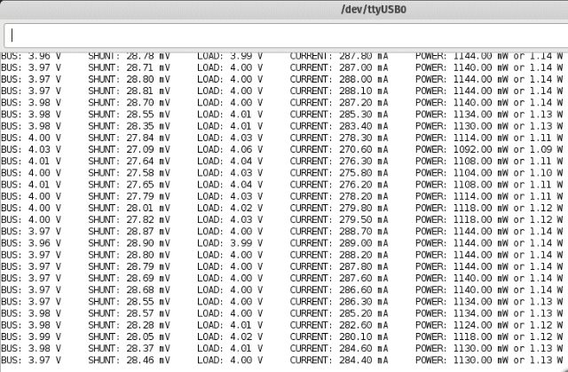
After the program has finished uploading, please open the serial monitor. Then, you will get the following readings:

If you want to see more example by this sensor, read here.
This is the basic tutorial for the INA219 current sensor from Arduino32, please modify the program for your needs and hope it is useful.
